Last updated: October 29, 2026 | By XHX Metal Engineering Team
Cable tray is the steel support system that carries electrical and data cables along a route: a shallow channel or ladder in 2 m or 3 m lengths, hot dip galvanised, suspended from the structure on hangers and joined with connectors and fittings. At XHX Metal, cable tray fabrication covers laser cutting, CNC punching, bending, welding and hot dip galvanising through audited partners in a 2,000 sqm factory in Dongguan, China.
This article is written for the electrical contractors and project buyers who order that system: what cable tray is made of, where it is used, how width, height and gauge are chosen, what actually goes wrong between the drawing and the installed run, how long a programme takes, what documents arrive with it, and three order examples with volumes and price bands.
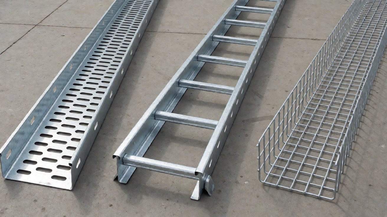
Figure 1: The three tray types side by side: perforated trough, ladder and wire mesh basket.
Cable Tray Fabrication: What We Build
The Three Tray Types
Cable tray comes in three forms and the choice of cable tray type is made on cable and environment rather than on price. Perforated trough tray is a shallow channel with a punched bottom and folded side rails, used for control and instrumentation cable where a closed bottom keeps dust and rodents out. Ladder tray has two side rails and open rungs, which suits power cable because it dissipates heat and lets cable drop out anywhere along the run. Wire mesh basket tray is a welded wire grid formed into a channel, the lightest of the three and common in data centres.
A single project often uses two types: trough for the control cabling and ladder for the power cabling, on the same route but on separate supports. Mixing them on one support is a common site shortcut that later causes interference complaints, because power and signal cable end up in the same channel.
The System, Not Just the Straight Section
A cable tray installation is mostly cable tray fittings. Straight sections run in 2 m or 3 m lengths, and between them sit 90 degree bends, tees, crossovers, reducers, risers and offsets, plus cover plates, dividers, connector plates and earth bonding jumpers. On a typical plant installation the fittings are 20 to 35 percent of the order value, and a supplier who can only ship straight sections leaves the contractor to source the rest.
That is the part of cable tray fabrication that is really being bought: the ability to deliver a complete route from one drawing set, with every fitting matching the straight sections in width, height and finish. A supplier who quotes the straight tray and leaves the fittings to someone else has quoted roughly two thirds of the job.
Where Our Scope Ends
The support structure is not ours. Threaded rods, channel brackets, anchors and the building steel are supplied by the contractor, and we make the tray that sits on them. What we own is the section geometry, the perforation, the welds, the galvanising and the fit between sections and fittings.
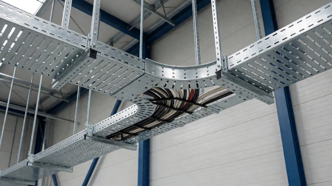
Figure 2: A galvanised trough tray installed on hangers, running through a 90 degree bend fitting.
Where Steel Cable Tray Is Used
Industrial Plants and Factories
The largest group of cable tray installations is industrial: factory power distribution, machine rooms, process plants, water treatment works and substations. These runs are long, they change direction often, and they are installed by a contractor working to an electrical drawing rather than to a product catalogue. Widths of 200 mm to 600 mm and trough or ladder type are typical. A plant cable tray package is usually ordered once, in two or three shipments timed to the installation programme, and the last shipment is the one that gets squeezed when the programme slips.
Industrial buyers also care about earthing continuity, because the tray is part of the protective bonding path and an inspector will test it. A galvanised tray run that is mechanically perfect can still fail that test at a joint where two coated surfaces are simply bolted together.
Data Centres, Telecom and Commercial Buildings
The second group is data and commercial: data halls, telecom rooms, offices, hospitals and airports. These favour wire mesh basket tray and lighter trough, often on trapeze hangers above a ceiling void, and the driver is cable density and access rather than mechanical load. In a data hall the tray is also expected to accept frequent changes, so basket is preferred because cable can be dropped in from above without disconnecting anything. That is a different product decision from an industrial run, where the tray is installed once and never touched again.
Infrastructure and Outdoor Routes
The third group is infrastructure: tunnels, metro, bridges, car parks and outdoor yards. These runs are exposed, so galvanising class and drainage matter more than appearance, and the tray often needs covers, dividers between power and data, and expansion joints where the structure moves. A tunnel run is usually the heaviest specification of the three, because access for maintenance is difficult and the tray has to last the life of the structure.
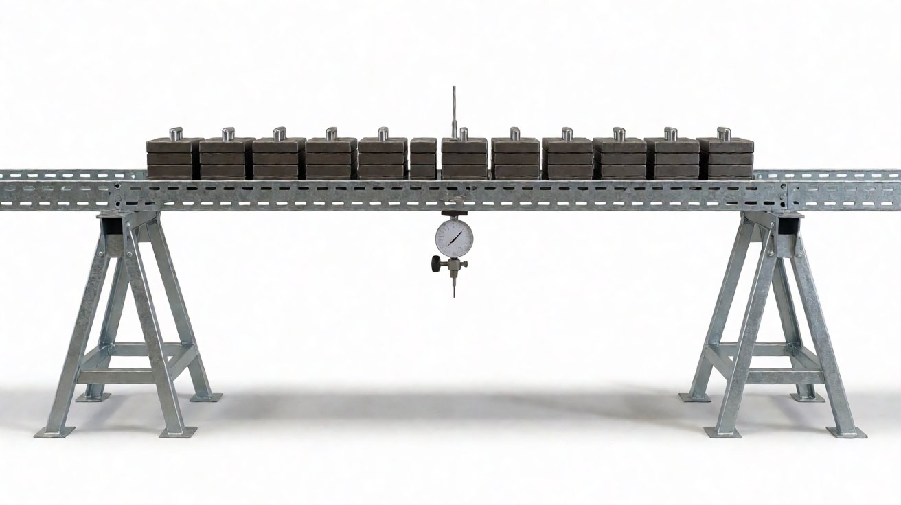
Figure 3: A load test on a straight tray section, measuring mid-span deflection under UDL.
Choosing Width, Height and Gauge
Fill Ratio and Width
What are the main quality risks in cable tray fabrication? The first is a section sized on habit rather than on cable fill. The working rule is that cable occupies no more than about 40 percent of the tray cross-section for power cable and around 50 percent for data, and the cable installation requirements behind those figures are set out in IEC 60364-5-52, which leaves room to add a circuit later and keeps heat dissipation workable. Width follows from the fill, and the common cable tray widths are 100, 200, 300, 400, 600 and 800 mm.
Height, the depth of the side rail on a cable tray, is a structural dimension rather than a cable one. A 100 mm rail is the default; 50 mm appears on light internal runs and 150 mm on long spans or heavy fill.
Gauge, Span and Load
The cable tray gauge has to be read together with the support spacing, because the tray is a beam between hangers and it deflects. Standard practice is a support every 1.5 m to 3 m, and the safe working load is quoted for a stated span and support condition, with the structural basis for the support design in EN 1993-1-3. A tray that carries 50 kg per metre at 1.5 m spacing will not carry the same load at 3 m, and a supplier who quotes a load without a span has not quoted anything.
Load testing for cable tray is defined in IEC 61537, which sets out the loading and deflection criteria a manufacturer has to demonstrate rather than assert.
Thickness, Finish and Environment
Sheet thickness for a steel cable tray runs from 1.0 mm on light internal basket and trough to 2.5 mm on wide heavy-duty trough, within the thickness tolerances of EN 10131. The thickness also sets the galvanising class, because the zinc coating thickness that a galvaniser can achieve depends on the steel thickness and the silicon content, so a thin sheet and a thick sheet do not come out of the bath with the same coating.
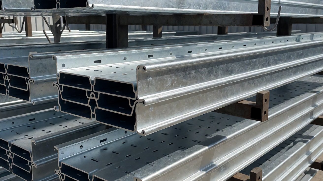
Figure 4: Tray sections after hot dip galvanising, the zinc spangle visible across the surface.
Punching, Forming and Galvanising
Perforation and Its Effect on Flatness
A trough cable tray is punched on a CNC punch press or a dedicated perforating line. The pattern is not decorative: the holes drain water, dissipate heat, save weight and take the cable ties. The land between holes matters structurally, because a bottom that is more hole than steel stops acting as a web and the tray loses stiffness.
Punching also distorts: closely spaced holes relieve stress unevenly and the blank can bow before it is folded, which is why the pattern and the punching sequence are set with the flat pattern.
Folding and Welding
The side rails are folded from the same blank as the bottom on a trough tray, which gives the section its stiffness without a weld along the length. Ladder tray is different: the rungs are separate parts welded between two formed rails, and the welding sequence alternates or the rail bows. Sheet steel for the sections is supplied to EN 10025-2.
Fittings are welded assemblies, and the tolerances on the folded parts follow ISO 2768.
Galvanising After Forming
Hot dip galvanising is the default finish for cable tray and it happens after every cut, punch, fold and weld, so the coating covers the cut edges and the inside of the section. Coating thickness is specified in ISO 1461, which sets the minimum average by steel thickness: roughly 55 microns under 1.5 mm, 70 microns from 1.5 to 3 mm, and 85 microns above 6 mm.
The bath is at about 450 C, and thin formed sections distort in it. Rails that were straight come out with a bow, and the practical flatness tolerance after galvanising is looser than after painting: around 8 mm per metre against 4 mm for a coated tray. Designing the section with enough fold stiffness and jigging it correctly in the bath is what keeps that under control.
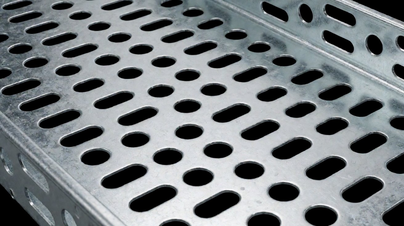
Figure 5: The perforated bottom of a trough tray, with the hole pattern and land width.
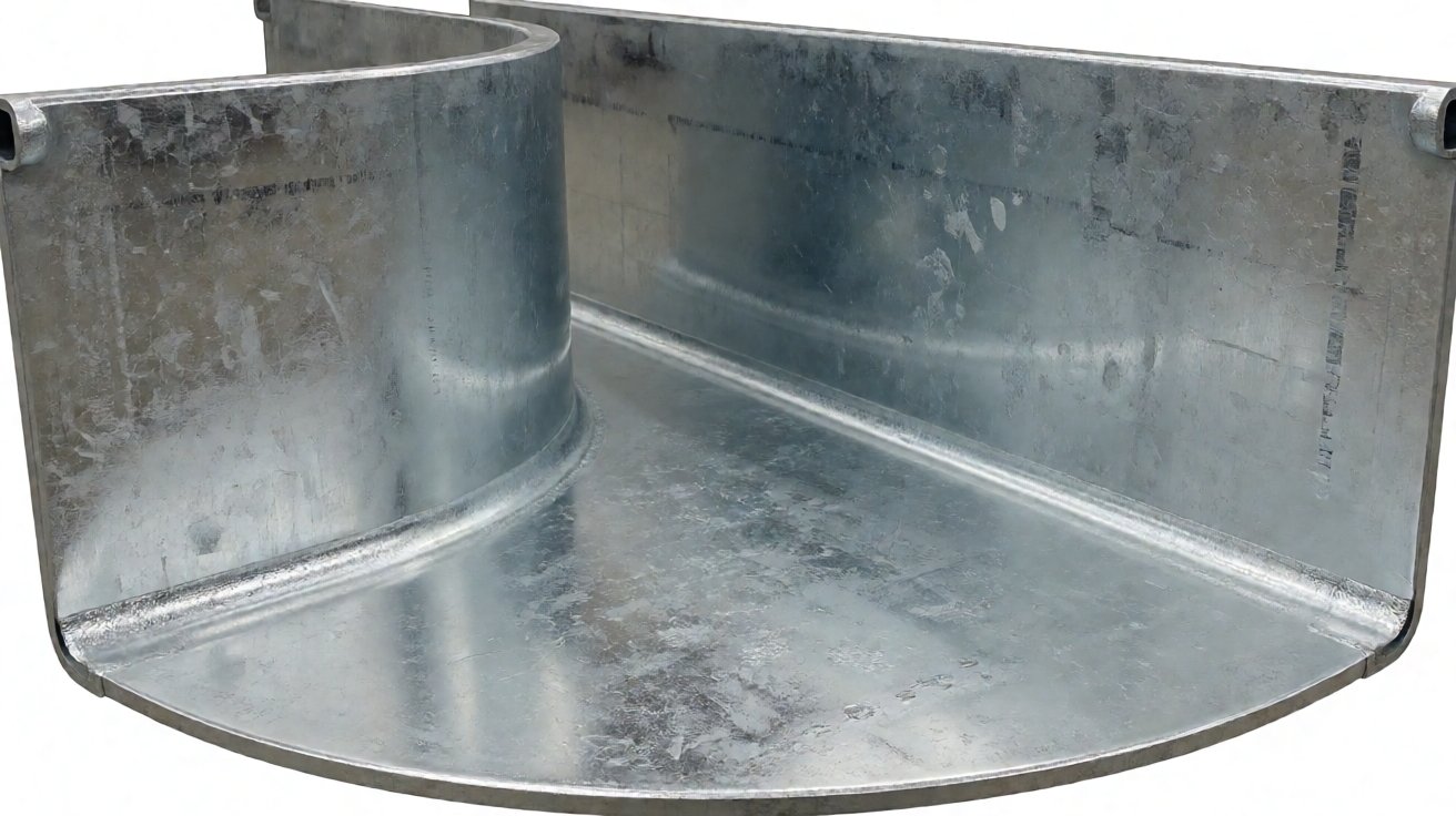
Figure 6: A 90 degree bend fitting, its side rails formed on a curve and the base welded in.
Earthing, Supports and Site Fit
Earthing Continuity
Cable tray is often part of the protective bonding path in a building, and the connection between two sections has to be electrically sound as well as mechanically tight. Galvanised surfaces are conductive, but a joint of plain bolts through coated steel can read high, so the specification usually calls for a bonding jumper across the joint or toothed washers that bite through the coating. Protective bonding requirements for installations are set out in IEC 60364.
The acceptance figure is a resistance across a jointed run, commonly 0.1 ohm or better between any two points, tested after installation rather than assumed from the drawing, using the continuity test methods described in IEC 61557-4. The test is quick and it is the one item on a cable tray inspection that regularly fails, because the bonding detail was left to site. Supplying the jumpers with the tray, and marking the joints that need one, removes the argument entirely.
Supports Do the Work
The tray only performs as well as its supports. A trapeze hanger with two threaded rods and a channel cross member is the common arrangement per the support details in EN 61537, and the spacing has to match the load case the tray was rated for. Hangers set further apart than the rating assumed is the single most common reason an installed tray sags under cable it was nominally able to carry. Where a run crosses a structural joint, an expansion joint in the tray is fitted so the tray slides rather than buckles. The same detail appears on long outdoor runs where the tray itself expands in summer, and it is routinely forgotten on projects that were designed indoors.
Site Fit and the Fitting List
Most site problems in cable tray come from the fitting list rather than the straight sections. A route drawn on a single line becomes, on site, a series of bends, offsets and reducers; if those were not ordered the contractor improvises by cutting and overlapping, which looks bad and breaks the earth continuity. The improvisation is visible to the client, which is why the fitting list is worth arguing about at quotation rather than at handover.
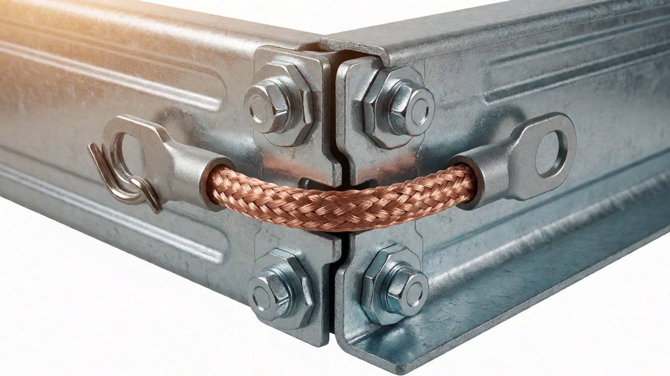
Figure 7: A joint between two tray sections with the connector plate and an earth bonding jumper.
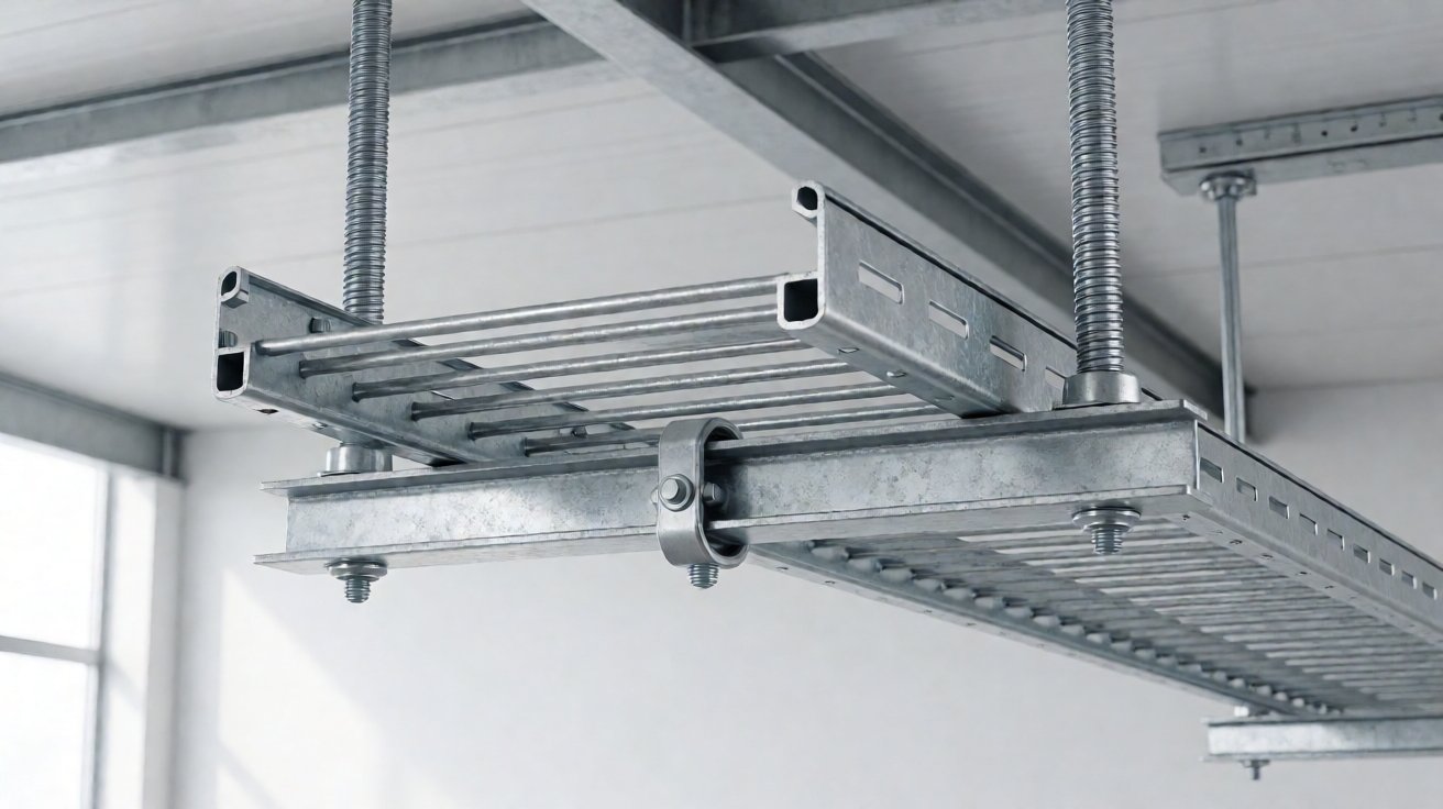
Figure 8: A trapeze support with threaded rods and a channel cross member carrying the tray.
Lead Time, Cost and the Order Process
From Drawing to Delivery
Cable tray fabrication starts with a route drawing and a cable schedule rather than with a product code. We ask for the route, the cable types and sizes, the fill, the support spacing the contractor intends to use, the environment, the required finish and the earthing requirement. From that we return a bill of straight sections and fittings with widths, heights and gauges.
That bill is the document that prevents site improvisation, because it forces every bend and reducer to be counted before the batch is cut. It also exposes the routes where the drawing is ambiguous: a line that appears to change level without an offset fitting is either a drawing error or a missing part, and it is much cheaper to find that at quoting than on site.
Documents You Should Receive
A cable tray order should arrive with the approved schedule, material certificates for the steel, the galvanising certificate with coating thickness readings, and the load rating statement with the span and support condition it applies to. On a project with an electrical inspector, the coating thickness record and the earthing method are the two documents that get asked for first. Where earthing is specified, the bonding method belongs on the drawing rather than in a note.
Batch Sizes and Price Bands
Cable tray of this kind is a project product rather than a stock item, and the order is driven by the installation programme rather than by a warehouse reorder point, priced against inspection documents per EN 10204. A plant or tunnel package runs from a few hundred metres to several kilometres, typically ordered in one or two releases, with the minimum order set by the galvanising batch rather than by the tray itself. FOB prices for a 300 x 100 mm hot dip galvanised trough tray typically fall between USD 7 and USD 16 per 3 m length depending on gauge, perforation and coating class, with fittings priced individually.
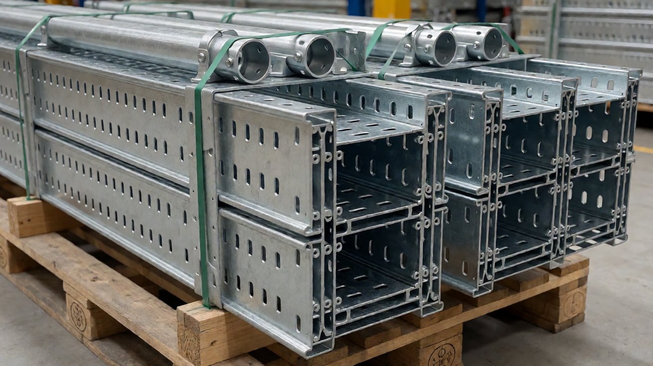
Figure 9: Tray sections stacked and bundled for export, nested to save freight volume.
Three Cable Tray Programmes
A Factory Distribution Package for a Middle East Contractor
An electrical contractor fitting out a food plant needed roughly 4 km of tray: 400 x 100 mm perforated trough for the main runs and 200 x 100 mm for the branches, hot dip galvanised, with a full fitting schedule and an earthing requirement across every joint.
We produced the cable tray as a single package with the straight sections nested for freight and every fitting matched in width, height and coating class, and supplied galvanising certificates per batch. Releases ran at two shipments of about 2 km each, with an MOQ of 500 m and FOB prices from USD 9 to USD 14 per 3 m length. The first shipment left 28 days after the schedule was approved and annual value was approximately USD 38,000.
A Data Hall Basket Tray Package for a European Integrator
A data centre integrator needed wire mesh basket tray for four data halls: 300 mm and 450 mm widths, electrogalvanised rather than hot dip because the halls were dry and the appearance mattered, with trapeze supports and a large number of tees and crossovers.
The cable tray was produced as basket sections welded on a fixture to keep the grid square, with fittings welded and de-burred so cable could not catch, and delivered in labelled bundles per hall. Releases ran at 1,200 m per hall across four halls, with an MOQ of 300 m and FOB prices from USD 11 to USD 19 per 3 m length. First delivery was 26 days after approval and annual value was approximately USD 26,000.
A Tunnel Ladder Tray Package for a Southeast Asian Project
A tunnel M&E contractor needed ladder tray for power cable in a road tunnel: 600 x 150 mm, 2.5 mm steel, heavy galvanising class because of the wash-down and humidity, with expansion joints and stainless fixings at the segment boundaries.
We produced the cable tray with rungs welded in an alternating sequence to keep the rails straight, heavier galvanising to class, and expansion joints matched to the segment joints. Releases ran at 1,500 m, once or twice a year, with an MOQ of 400 m and FOB prices from USD 22 to USD 34 per 3 m length. The first shipment left 32 days after approval and annual value was approximately USD 30,000.
Choosing a Cable Tray Supplier
What to Ask at Quotation
Ask five things before comparing prices for cable tray. What gauge and what galvanising class are quoted, and does the class match the steel thickness? Is the load rating stated with the span and support condition it applies to? Is the fitting schedule included, or are straight sections only? Is the earthing method on the drawing, and are bonding jumpers supplied? And is the tray nested or crated for freight?
The answers separate suppliers quickly. A quote that names the gauge, the coating class, the span behind the load rating and the fitting count is comparable; a quote that lists a width and a price per metre is not, because the same nominal tray can be built to carry half the load and last half as long.
Where Suppliers Fail
Failures in cable tray supply cluster in five places. Sections arrive bowed because thin formed steel was galvanised without jigging. Coating is under the specified class because the gauge was changed and nobody revisited the galvanising. A run cannot be completed because the fittings were never ordered. Earth continuity fails the test because the joints rely on coated steel touching coated steel. And the tray deflects in service because the load rating was quoted for a shorter span than the contractor used.
None of these are exotic. They follow from buying cable tray as a commodity length of steel rather than as a rated system, and they are avoided by stating the span, the coating class and the fitting schedule at enquiry.
How XHX Metal Works
XHX Metal has manufactured sheet metal products for export customers from Dongguan since 2014, in a 2,000 sqm factory with about 30 staff. The equipment list covers two 6 kW fiber laser cutting machines at +-0.01 mm, CNC punching, CNC bending, TIG and MIG welding, and hot dip galvanising and powder coating through audited partners, all under ISO 9001:2015 with CE documentation and SGS records.
For a cable tray programme, samples follow in 5 to 10 working days and first batches in 20 to 30 days depending on the galvanising. Send a route drawing and cable schedule with the fill, the support spacing and the environment through the contact page; related work is described on the CNC punching page and the sheet metal capabilities page, and enquiries also reach sales01@xinghaoxin.com.
Frequently Asked Questions
What is cable tray?
It is the steel support system that carries electrical and data cable along a route: a shallow perforated channel, an open ladder or a wire mesh basket, supplied in 2 m or 3 m lengths with bends, tees and reducers, suspended from the structure on hangers.
Which tray type should I use?
Perforated trough for control and instrumentation cable where a closed bottom is wanted, ladder for power cable because it dissipates heat and allows cable to drop out, and wire mesh basket for data halls where weight and access matter more than load.
How do I size cable tray?
Start from the cable fill: keep cable to about 40 percent of the cross-section for power and 50 percent for data, then choose the width. Height is structural rather than cable related, and the gauge has to be read together with the support spacing.
What is the safe working load of a cable tray?
It is only meaningful with a span and support condition attached. Load testing is defined in IEC 61537, and a supplier should state the rating for a stated span rather than a single number.
How thick is hot dip galvanising on cable tray?
ISO 1461 sets the minimum average by steel thickness: about 55 microns on steel under 1.5 mm, 70 microns from 1.5 to 3 mm, and 85 microns above 6 mm. The coating is applied after cutting, punching and welding so the cut edges are covered.
How long does cable tray fabrication take?
Samples follow in 5 to 10 working days after the schedule is approved. First production batches ship in 20 to 30 days depending on quantity and galvanising.