Industrial fan and blower housing manufacturing is the sheet metal discipline behind the scroll casings, circular shells, and shrouds that move air in factories, buildings, and process plants. A housing is more than a shell: its geometry defines how the impeller performs, how much air moves at a given pressure, and how much noise the fan makes, which is why AMCA International publishes performance rating standards for air movement equipment and SMACNA sets fabrication practice for air systems. Getting the housing right is a precision engineering job, not a cut-and-bend afterthought.
This guide follows the full journey of a custom fan housing program in seven steps: the product and its housing families, the applications each serves, material selection, production difficulty, lead times, past case studies with real purchasing data, and a practical summary. Whether you are a ventilation OEM sourcing volute casings, an HVAC manufacturer buying axial fan housings, or a project buyer specifying large casings for dust collection, the information here will help you brief a fabricator, plan realistic timelines, and avoid the geometry and balance problems that show up at final testing.
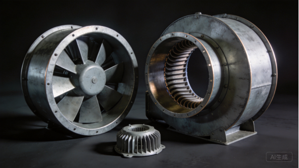
Figure 1: Industrial fan and blower housings in galvanized and painted construction.
The Product: What Are Industrial Fan and Blower Housings
Fan Types and Housing Families
Industrial fans fall into three main families: axial, centrifugal, and mixed-flow. Axial fans move air along the shaft axis and use simple circular or box housings with a motor mount and guard; centrifugal fans turn air through ninety degrees and use spiral volute casings that convert velocity into pressure; and mixed-flow designs combine both behaviors in compact housings. Each family has its own housing geometry and manufacturing logic.
Within each family, housings vary by size, duty, and inlet arrangement. A small axial fan housing may be a rolled ring with welded brackets, while a large centrifugal volute can be built from several rolled and welded segments with flanged inlets and outlets. Industrial fan and blower housing manufacturing spans all of these, and a fabricator that handles rolling, welding, and flanging can supply the full housing range to fan OEMs.
Core Components and Their Roles
The core components of a fan housing are the casing, the inlet cone or ring, the outlet flange, the motor mount, and the guards. The casing contains the impeller and shapes the airflow: in a centrifugal fan, the volute scroll collects air around the impeller and delivers it to the outlet with minimum loss. The inlet ring guides air into the impeller eye, and the outlet flange connects to ductwork with a clean transition.
The motor mount and bearing supports carry the drive train and must align with the impeller within tight limits, because misalignment causes vibration and early bearing failure. Guards and screens protect personnel where the impeller is exposed. Every component is a fit point, and the housing design must hold tolerances so the impeller spins true, the flanges mate with ducts, and the fan runs quietly through its service life.
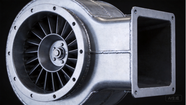
Figure 2: A volute casing cutaway shows the scroll passage, inlet, and outlet geometry.
Design Drivers: Airflow, Pressure, and Noise
Fan housing design is driven by the performance curve: the airflow and static pressure the fan must deliver at its operating point. The volute geometry, the clearance between impeller and casing, and the inlet shape all affect efficiency and pressure development, and small geometry changes show up as measurable performance differences. AMCA performance testing standards give buyers a common way to verify that a fan meets its rating.
Noise is the second design driver. Housing geometry influences aerodynamic noise, and vibration paths from the impeller through the casing and mounts determine how much structure-borne sound reaches the building. ASHRAE guidance on ventilation system design covers acoustic treatment, and the housing is designed with stiffening, insulation options, and clean airflow paths. These drivers are settled at the drawing stage, not discovered at the first sound test.
Customization in Industrial Fan and Blower Housing Manufacturing
Custom industrial fan and blower housing manufacturing exists because every fan application has its own flow, pressure, and envelope. Buyers customize casing dimensions, inlet and outlet orientations, flange drilling, motor mount positions, and materials for the duty, and they expect housings that match their impellers and drive trains. Custom fabrication also supports product families: one volute profile can serve several impeller widths and speeds.
Customization includes compliance details such as guards that meet safety requirements, flanges that match standard duct dimensions, and surface treatments for the environment. OSHA sets expectations for machine guarding and workplace ventilation, and buyers increasingly ask for documented materials and inspection evidence. A fabricator that can provide material certifications and consistent batch quality gives fan OEMs the file they need for performance and safety claims.
Use Cases and Applications
Industrial Ventilation and Exhaust
Industrial ventilation is the largest market for fan housings. Factories use wall and roof exhaust fans to remove heat, fumes, and stale air, and supply fans to bring in fresh air, with housings sized to the building’s air-change requirement, and industrial fan and blower housing manufacturing serves this demand with galvanized construction built for long service in demanding conditions.
Ventilation programs follow airflow and noise targets defined by the facility design, and the housing must deliver the rated performance within the space available on a wall or roof. SMACNA fabrication standards guide the duct and housing connections, and buyers expect housings that match standard duct sizes and flanges. For manufacturers, ventilation OEMs order in volume and reorder as projects are won, which builds steady, repeatable demand.
Dust Collection and Material Handling
Dust collection and material handling systems use fans that move abrasive or particulate-laden air, and the housings must resist wear and maintain performance under heavy duty. Centrifugal fans with heavier casings, abrasion-resistant liners, and carefully sealed joints serve these systems, and the housing geometry is designed for the pressure requirements of long duct runs.
Dust collection projects are often engineered to order: the fan is sized from the duct design, and the housing is built to match a specific duty point. Buyers need documentation of materials and construction, and the housings must assemble with the system’s inlet and outlet connections. For fabricators, these projects are lower volume but higher margin, and they demonstrate the rolling and welding capability that industrial customers value.
Dust collection systems also require reliable seals at joints, because leaks allow dust into the workplace and reduce collection efficiency, so the housing and flange construction is documented for the system designer.
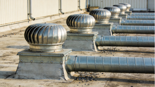
Figure 3: Roof exhaust fan housings connect to duct systems across industrial facilities.
HVAC and Commercial Ventilation
HVAC and commercial ventilation use fans in air handling units, exhaust systems, and parking garage ventilation, where efficiency and noise matter. Housings for these fans are built to fit the equipment envelope, with flanged connections and motor mounting that simplify assembly, and the casing design supports the efficiency the project’s energy budget requires.
HVAC programs follow standards and code requirements: ASHRAE provides design guidance, and efficiency programs increasingly set minimum fan performance. Housings must be documented for the ratings claimed, and consistent geometry across units keeps performance repeatable. For manufacturers, HVAC OEMs buy housings in production volumes against equipment schedules, which rewards reliable delivery and quality.
Process and Specialty Fans
Process and specialty fans move air in specific duties: combustion air, cooling, fume extraction, and marine ventilation. These applications often use stainless or coated housings, explosion-proof construction, and materials matched to the process environment, and the housing must survive temperature, chemicals, or corrosive atmospheres that standard ventilation never sees.
Specialty programs are specification-driven. Buyers need material certifications, weld documentation, and construction details that match the duty, and the fabricator’s ability to handle stainless, coatings, and tight geometry wins the order. For fabricators, specialty work is lower volume but high-value, and it builds the capability profile that wins larger commercial programs.
For fabricators, these specification-driven orders build references that open doors in the wider fan market.
Material Selection
Cold-Rolled and Galvanized Steel
In industrial fan and blower housing manufacturing, cold-rolled and galvanized steel are the default materials. Galvanized steel resists corrosion from moisture and general industrial atmospheres, and its zinc coating protects cut edges sacrificially, which matters on rolled edges and welded joints. The American Galvanizers Association documents decades of service for galvanized coatings, and typical housing thicknesses range from 1.2 mm for small fans to 3.0 mm for large industrial casings.
Cold-rolled steel is used where the housing will be painted, and its mechanical properties are documented in references such as MatWeb’s materials database for comparison. Both materials roll, weld, and flange predictably, which keeps the fabrication process repeatable across housing sizes. For most ventilation and HVAC applications, galvanized steel is the cost-effective standard, with stainless reserved for corrosive and process duties.
Housing thickness is also a structural decision: large casings and high-pressure fans need thicker shells to resist deflection, and the thickness is matched to the duty point rather than chosen by habit.
Stainless Steel
Stainless steel, primarily grades 304 and 316, is specified for fan housings in food, pharmaceutical, chemical, marine, and corrosive process environments. SSINA provides grade selection guidance for corrosive service, with grade 316 adding molybdenum for chloride resistance. Stainless housings never need recoating, tolerate washdown and chemicals, and present the clean surface that hygienic industries require.
Stainless is more expensive and harder to form than carbon steel, and it demands dedicated handling to prevent contamination that causes surface rust. Welds must be controlled and finished to preserve corrosion resistance, and the extra material cost is justified by service life in demanding duties. For fabricators, stainless capability is a differentiator that wins process and food-industry programs.
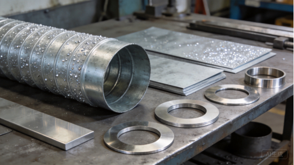
Figure 4: Rolled shells, flat sheets, and inlet blanks cover the fan housing material range.
Aluminum
Aluminum housings appear where weight, corrosion, or spark resistance matters: marine ventilation, portable units, and hazardous locations where non-sparking construction is required. Aluminum is about one-third the weight of steel, resists corrosion naturally, and its properties and alloy selection guidance are cataloged by references such as AZoMaterials.
The trade-offs are strength and cost: aluminum housings need thicker sections to reach the same stiffness, and the material costs more per kilogram. Welding aluminum requires controlled heat input to avoid distortion, and galvanic isolation is needed at joints with steel hardware. For weight-critical and non-sparking applications, aluminum is often the right choice despite the premium.
Coatings, Gaskets, and Hardware
The finish protects the housing and defines its service life. Powder coating adds color and durability for painted housings, and the Powder Coating Institute publishes technical resources on coating selection and testing, with performance verified under ASTM International standards including salt spray and adhesion tests. Gaskets seal flanged connections where leakage matters, and fasteners and guards are selected for the environment.
For process and outdoor duties, the coating and hardware specification is part of the engineering: high-temperature duties may need heat-resistant coatings, and corrosive atmospheres call for stainless hardware. Agreeing the finish, gasket, and hardware specification at quotation prevents the most common field complaints, rusted fasteners and leaking flanges, before the fan ships.
For high-temperature process fans, thermal expansion of the casing is designed into the flange and mount geometry.
Production Difficulty
Laser Cutting and Blank Development
Industrial fan and blower housing manufacturing begins with laser cutting, which produces the flat blanks that become casing sections, inlet rings, flanges, and brackets. Fiber laser systems hold tolerances around plus or minus 0.1 mm, and at XHX Metal two 6kW fiber laser cutting machines deliver plus or minus 0.01 mm positioning accuracy, which matters when flange bolt circles and inlet openings must line up with ductwork.
Blank development is where housing geometry starts: the volute is developed from the scroll curve, and the flat pattern must account for the bend allowance of the rolled sheet. Engineers Edge publishes mechanical references used in sheet development, and nesting software arranges parts to minimize scrap across the housing set. The cutting stage decides whether the rolled shell forms to the right radius and the flanges mate cleanly.
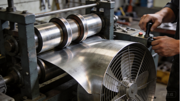
Figure 5: Plate rolling curves housing shells to the volute geometry.
Rolling, Forming, and Volute Geometry
Rolling is the defining process of fan housing work: plate rollers curve the flat blank into the casing shell, and the roll radius must match the design so the assembled volute follows the scroll. TWI Global provides technical guidance on forming and welding steel, and the rolling sequence, edge preparation, and springback are controlled to produce a true cylinder or scroll section. This forming stage is the core of industrial fan and blower housing manufacturing.
For centrifugal volutes, the casing is often built from several rolled segments welded together, and the segment joints must blend so the internal passage is smooth. Flanging, beading, and forming the inlet cone follow, and each operation is checked against the drawing. The rolling and forming stage is where fan geometry is won or lost, and it is the capability that separates fan housing work from general sheet metal fabrication.
Welding, Flanges, and Assembly
Welding joins the casing segments, attaches flanges, brackets, and motor mounts, and seals the housing against leakage. Heat from welding can distort rolled shells, so parts are clamped and sequenced to control shrinkage, and continuous welds at seams prevent air leaks that reduce fan performance. Flanges are welded square to the casing so duct connections mate without stress.
Assembly adds the inlet ring, guards, and drive components, and the housing is checked for roundness, flatness, and alignment before the impeller is fitted. For OEMs that assemble the fan themselves, the fabricator ships housings ready for their impellers and motors. Fixture-based assembly with documented checks keeps quality consistent across housing sizes, and this discipline is what lets fans run true at final test.
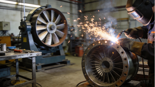
Figure 6: Flange welding and dynamic balancing keep fan assemblies true.
Quality Control and Performance Verification
Fan housing quality control combines dimensional inspection with functional verification. First articles are inspected against the drawing, verifying casing roundness, flange squareness, and bolt circles, and production batches follow a control plan with sampling. Weld quality is checked on pressure-critical seams, and coating thickness is verified on painted units.
Performance verification is the fan-specific step: the housing is tested with an impeller to confirm airflow, pressure, and noise against the rating, using methods consistent with AMCA practice. Vibration and balance checks confirm the housing aligns the drive train. A fabricator that coordinates performance testing gives fan OEMs the evidence they need for ratings and project approvals, which is a real advantage in the air movement industry.
Production Lead Times
RFQ, Engineering Review, and Prototypes
A fan housing program starts with an RFQ: drawings or performance specification, material, finish, quantities, and target timing. The fabricator’s engineering team reviews the design for manufacturability, checking roll radius, weld access, flange fit, and material choice, and returns a quotation with comments within one to three business days. Prototypes are typically delivered in ten to twenty business days because rolling and welding programs must be prepared.
The prototype is where housing geometry gets validated: the volute is rolled and welded, the impeller is fitted, and the flange connections are checked. Prototype feedback should include fit notes and suggested drawing changes. For fan programs, a fully assembled sample with an impeller, not just the shell, is worth the cost because it proves the housing performs before production begins.
Buyers with standard fan ranges benefit from previously approved housing drawings, which cut the engineering review to a confirmation check.
Tooling and Process Setup
Most fan housings are produced with laser cutting, plate rolling, and welding, which keeps tooling costs low and design changes inexpensive. The setup that matters is process tooling: rolling programs with verified radii, welding fixtures for casing segments and flanges, and inspection templates for bolt circles and roundness. Building this setup typically takes one to two weeks for a new housing size.
For very high volumes, dedicated fixtures and gauges can speed production, but fan housing volumes usually support flexible fabrication with a cost comparison at quotation. Buyers should expect the fabricator to review tooling economics rather than assume expensive dies are necessary.
Standard housing sizes can often reuse existing rolling programs and welding fixtures, which shortens setup time for repeat orders.
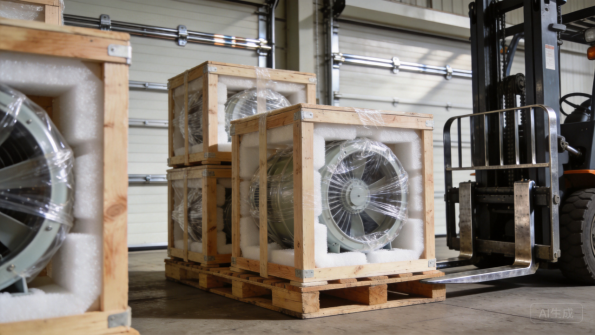
Figure 7: Rolled shells and crated casings ship with protective packaging for export.
Production Batches and Volume Planning
In industrial fan and blower housing manufacturing, typical production lead times are 20 to 35 business days for batches from a few dozen to several thousand housings, with rolling, welding, and coating consuming the largest share of that time. Larger casings take longer because they are built from more segments and require more handling.
Forecast sharing keeps lead times stable. When OEMs share rolling forecasts, the factory reserves material and coating capacity and orders long-lead items such as specific stainless grades in advance. Galvanized and cold-rolled coils are usually on hand, while stainless sheets and custom finishes may add one to two weeks. A clear schedule with milestone dates makes the bottleneck visible before it becomes a production delay.
Packaging, Logistics, and Documentation
Fan housings ship in packaging matched to the product: rolled shells protected by film and foam, flanges covered against impact, and large casings crated for container loading. Export shipments use rust-preventive paper or VCI film against container condensation, and the fabricator should provide crate dimensions, gross weight, and loading photos for freight planning.
Documentation accompanies every shipment: packing lists, material certificates, weld and coating records, and dimensional reports where agreed. Buyers should confirm the documentation set during quotation, because fan projects often require records for the performance file. Communication follows clear milestones, with photos at each stage, so OEMs and project buyers can track progress without site visits.
For project buyers, container loading plans are agreed at quotation so the casing sizes fit the freight budget.
Past Case Studies
European Ventilation OEM: Centrifugal Volute Casings
In industrial fan and blower housing manufacturing, a European ventilation OEM sourced centrifugal volute casings for its fan range, covering sizes from 200 mm to 630 mm in 1.5 mm galvanized steel. The initial order was 120 units as a pilot at FOB prices of $88 to $145 per casing depending on size, and the program grew to an annual volume of about 3,200 casings, worth roughly $360,000 per year, with a minimum order quantity of 120 units per size.
XHX Metal built the casings with rolled segments, welded flanges, and powder-coated finishes, and delivered the first production batch in 28 business days, shipped as part of a shared 20-foot container. After 12 months, rolling and blank-nesting improvements reduced unit cost by 5 percent, which the OEM passed into its pricing. The program now runs on monthly releases against a rolling forecast, with performance and dimensional records accompanying each batch.
North American HVAC Manufacturer: Axial Fan Housings
A North American HVAC manufacturer needed axial fan housings from 250 mm to 500 mm diameter, about 8,000 units a year at a monthly average of 650 units, with a minimum order of 300 units. Unit prices ranged from $12 to $28 depending on diameter, giving an annual purchasing value of roughly $160,000, and the housings shipped with guards, motor brackets, and mounting flanges ready for the OEM’s assembly line.
The first articles were dimensionally verified and a pilot batch of 350 units was delivered in 22 business days. In month nine, material and nesting improvements cut unit cost by 6 percent, and the OEM converted the program to a monthly blanket order with agreed stock levels. The program showed how industrial fan and blower housing manufacturing scales to blanket-order volumes, and the housings are now delivered as part of the OEM’s standard production schedule with packing lists and material certificates on every shipment.
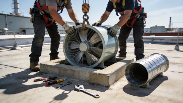
Figure 8: Axial fan housings are installed and connected on factory roofs.
Kitchen Exhaust Equipment Maker: Stainless Shrouds
A kitchen exhaust equipment maker needed stainless steel fan shrouds in grade 304, 1.0 mm, for commercial range hood systems, with welded seams, brushed finishes, and flanged connections for ductwork. The annual requirement was about 600 shrouds with a minimum order of 60 units, priced from $180 to $320 FOB depending on size, for an annual value of roughly $150,000.
XHX Metal produced the first articles with weld and finish verification, and the first batch of 120 shrouds shipped in 32 business days in a full container with SGS inspection at the factory. The customer’s quality team approved the finish samples before volume production, and the program now delivers quarterly releases with material certificates and finish records. The shrouds pass the customer’s grease-laden air tests and have been specified on two equipment lines.
Dust Collection Project: Large Diameter Casings
A dust collection system integrator needed large centrifugal fan casings from 800 mm to 1,250 mm diameter for a plant project, built from 3.0 mm galvanized steel in segmented construction. The order covered 50 production casings plus 20 spare parts, priced from $450 to $980 FOB depending on size, for a total value of about $85,000, shipped in two 40-foot containers.
The casings were manufactured in segments with welded flanges and shipped with assembly drawings for on-site joining, and the first article was fitted with the project’s impeller to confirm the scroll geometry. Delivery was completed in 34 business days, and the integrator used the same housing design on a second plant. The program showed how large-diameter rolling and segmented construction serve engineered-to-order dust collection projects.
Summary and Next Steps
Key Takeaways
Industrial fan and blower housing manufacturing is a geometry-sensitive discipline that demands more than sheet metal work. The material decision drives cost and performance, from galvanized steel for ventilation to stainless for process duties, and the rolling, welding, and flanging processes decide whether the housing performs to its rating. Production difficulty concentrates in volute geometry, rolling accuracy, and welded seal quality, which are exactly where experienced fabricators differentiate themselves.
Lead times follow a predictable path: engineering review in days, prototypes in two to four weeks, process tooling in one to two weeks, and production in three to five weeks per batch. Forecast sharing and staged delivery planning keep OEM and project programs on schedule. Buyers who settle materials, performance targets, and documentation requirements before quoting will have smoother programs than those who discover requirements at final testing.
Why XHX Metal
XHX Metal is a privately owned sheet metal manufacturer in Dongguan, China, with a 2,000 square meter factory, about 30 employees, and an annual capacity exceeding 500,000 pieces. The factory operates under an ISO 9001:2015 quality management system with CE and SGS certifications, and it produces custom housings, casings, enclosures, and fabricated parts for export customers with packaging designed for ocean freight. Two 6kW fiber laser cutting machines, plate rolling, CNC press brakes, and TIG and MIG welding cover the fabrication side of fan housing work.
The company supports buyers from design review through production, provides first-article inspection reports and material certificates, and coordinates coating, dimensional, and performance verification when required. For industrial fan and blower housing manufacturing programs, buyers can review related sheet metal fabrication services and product pages, and the team will structure quotations, quality documentation, and delivery schedules to match the program’s needs.
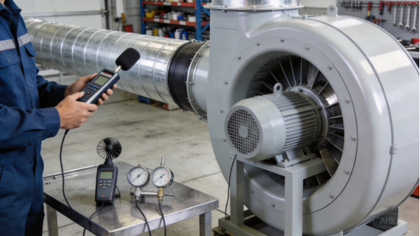
Figure 9: Performance testing verifies airflow, pressure, and noise before shipment.
How to Start Your Project
Start with a STEP or STP file and a drawing that states material, finish, performance targets, quantities, and documentation requirements. If the design is not finalized, send photos or sketches of the fan, the impeller diameter and speed, the duty point, and the annual volume, and the engineering team will recommend a manufacturable, rating-ready design. The typical path is: engineering review, quotation, prototype, first-article inspection, production, and shipment, with clear communication at each milestone.
To discuss a fan housing program, contact Barry at +86 13244963694 or sales01@xinghaoxin.com, or send your design through the XHX Metal website. With clear requirements and the right partner, an industrial fan housing moves from drawing to production in weeks, with geometry and welded quality that pass performance testing.
What to Ask a Fabricator
Before placing an order, ask the fabricator three questions: which materials and thicknesses it rolls and welds regularly, how it verifies casing roundness and flange squareness on first articles, and what performance, weld, and coating documentation it can provide. The answers reveal whether the shop treats fan housings as air-moving components or as simple metal boxes.
Also confirm rolling capacity for large diameters, segmented construction experience, and export packaging, because those details decide whether a housing arrives true and on schedule. A fabricator that lists test methods and acceptance criteria in the quotation is treating quality as part of the product, and that is the partner worth building a fan line with.