Last updated: October 26, 2026 | By XHX Metal Engineering Team
An amplifier chassis is the sheet metal housing that carries an audio amplifier, a preamplifier or a rack-mounted audio processor: it locates the transformer, the boards and the heat sinks, provides the front panel the user sees, and removes the heat those components generate. At XHX Metal, amplifier chassis fabrication covers laser cutting, CNC punching, bending, spot and TIG welding, powder coating and screen printing in a 2,000 sqm factory in Dongguan, China.
This article is written for the engineers and buyers who specify that housing: what an amplifier chassis is made of, where it is used, how gauge and material are chosen, what actually goes wrong on an audio enclosure, how long a programme takes, what documents arrive with it, and three order examples with volumes and price bands.
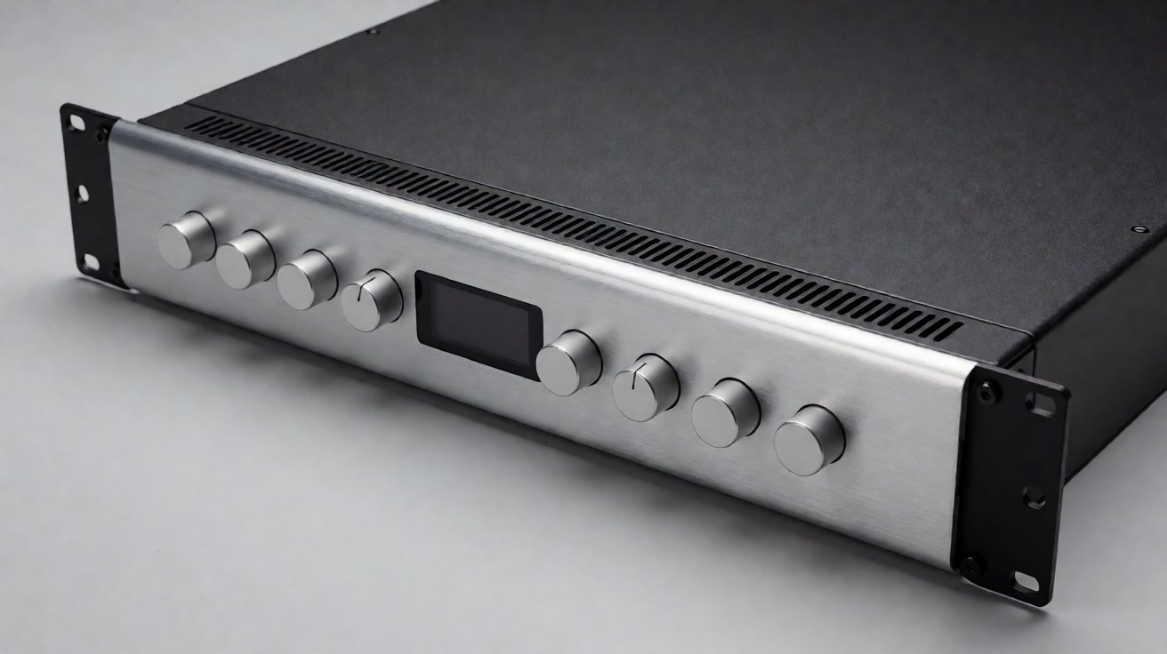
Figure 1: A finished rack-mount amplifier chassis in black powder coat, front panel fitted.
Amplifier Chassis: What We Build
The Parts in a Chassis Order
A typical order for an amplifier chassis contains a base, a U-shaped cover, a front panel, a rear panel, two side cheeks or a folded wrap, mounting ears for rack use, and the internal brackets that hold the transformer and the heat sink. The base is the structural part; the cover is mostly a lid, and the front panel is mostly appearance.
Splitting the box that way matters because each part is judged on a different criterion. The base has to be stiff and flat, the cover has to be stiff and vented, and the front panel has to be flat enough to look machined rather than folded. A supplier who quotes one gauge for the whole amplifier chassis has not understood that, because the three parts do different jobs.
Three Problems, Not One
An amplifier chassis is unusual among sheet metal enclosures because it has three separate physical jobs, and a design that solves one often makes another worse. It has to resist resonance, because a panel that rings colours the sound and buzzes at certain notes. It has to shield, because a mains transformer and a switching supply radiate into the signal path. And it has to remove heat, because a class AB amplifier dissipates a large fraction of what it draws. Panel vibration measurement practice follows ISO 7626.
Adding stiffness by thickening the panel adds mass, which lowers the resonant frequency into the audible band. Adding ventilation removes metal, which reduces shielding. And bonding the panels for shielding means breaking the coating, which is where corrosion starts. This is why an audio chassis is a design conversation rather than a cut list, and why the vent pattern, the rib layout and the earth points belong on the same drawing.
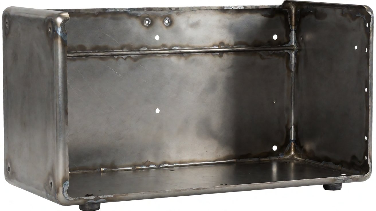
Figure 2: The bare folded shell before finishing, showing the return flanges and weld points.
Where Our Scope Ends
The electronics are not ours. Transformers, boards, heat sinks, connectors and the final assembly are the customer’s scope; we fabricate the metal, the finish and the printing, and we can fit hardware such as standoffs, earth studs and captive nuts. What we own is the stiffness, the fit, the flatness of the visible faces and the continuity of the shielding.
Where Amplifier Chassis Are Used
Professional Audio and Install Sound
The largest group is professional audio: power amplifiers for touring rigs, install amplifiers for bars, churches and conference rooms, and the DSP and matrix processors that sit beside them. Because these share a rack, the amplifier chassis and the processor chassis are usually designed together so the front panels line up. These are almost always 19-inch rack units, so the height is quoted in rack units (1U, 2U, 3U) and the width is fixed by the rack standard, which is defined in IEC 60297.
Touring equipment also has to survive being loaded and unloaded, so the chassis takes handling loads that a fixed install never sees, and the mounting ears are the part that fails first if the gauge is chosen on cost. An ear that bends under a loaded rack drops the whole unit, which is why the ears on a touring amplifier chassis are usually a heavier gauge than the shell or a separate folded bracket.
Hi-Fi, Studio and Instrument Amplifiers
The second group is consumer and studio audio: hi-fi power amplifiers, phono stages, headphone amplifiers, guitar and bass heads, and studio monitor amplifiers. These care more about appearance and about resonance than about rack fit, and the front panel becomes the product: brushed aluminium, machined edges and printed legends are normal rather than optional. A hi-fi buyer judges the amplifier chassis by the panel gap and the grain direction before they hear it, so the cosmetic tolerance is tighter than on any install product.
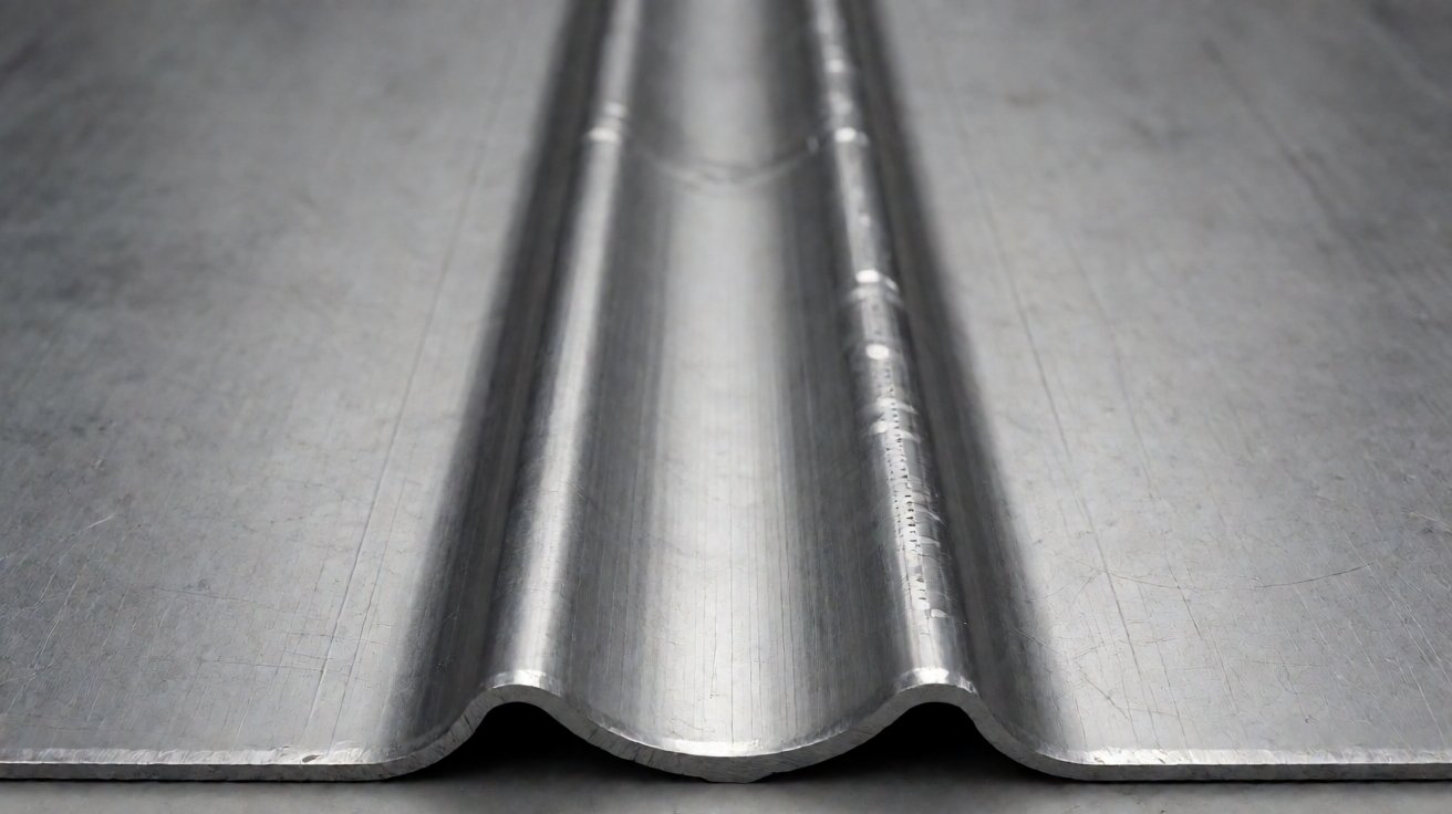
Figure 3: A swaged stiffening rib across the base panel, the detail that moves the resonance peak.
Vehicle, Marine and Specialty Audio
The third group works in a hostile environment: car audio amplifiers, marine audio, public address units and emergency announcement equipment. These add vibration, corrosion and often a sealed enclosure, and the chassis takes on the character of an environmental enclosure rather than a piece of furniture. Ventilation may be removed altogether and the heat path routed through the base into the mounting surface, which changes the design completely.
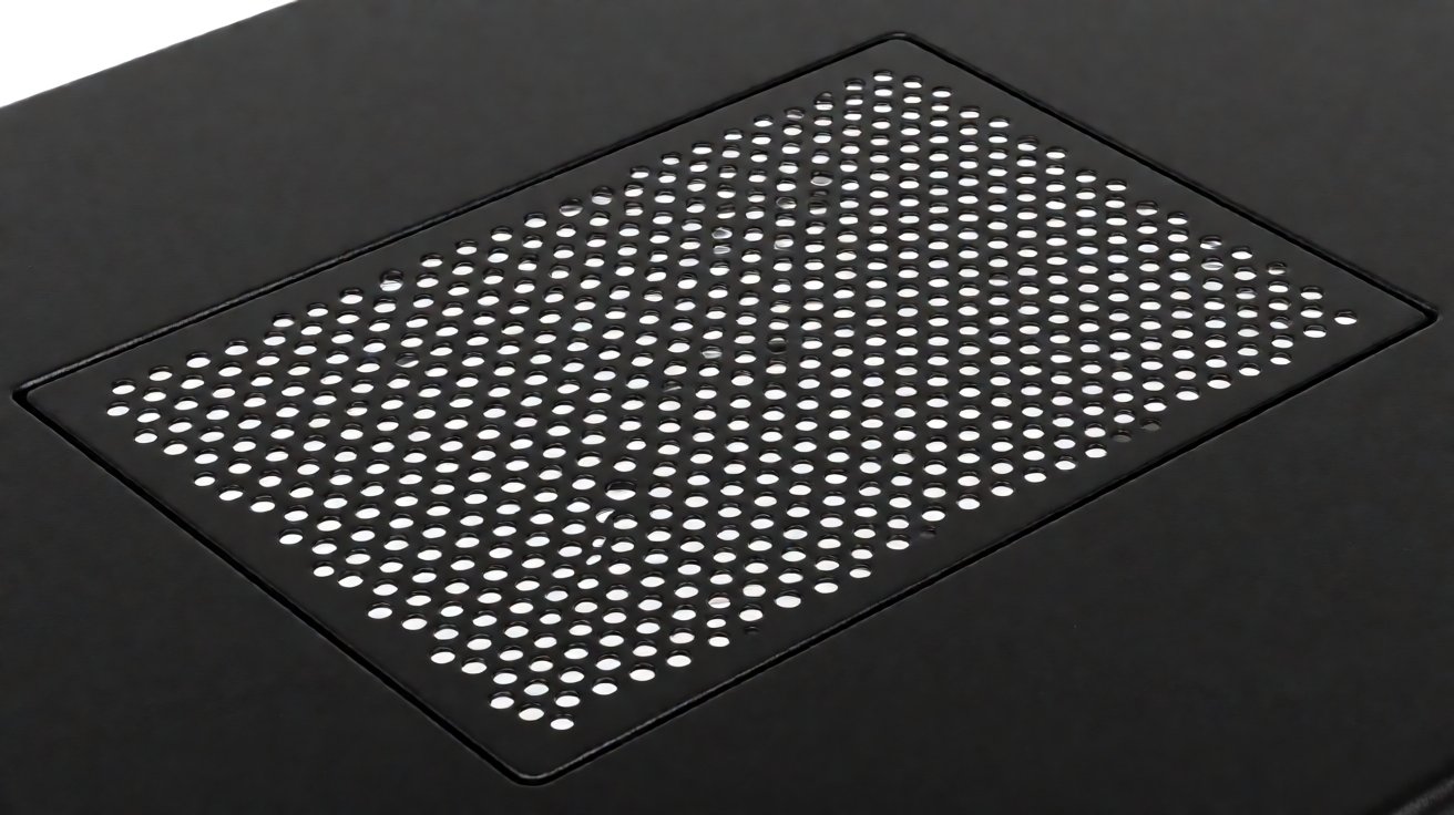
Figure 4: A family of chassis in 1U, 2U and 3U heights side by side for comparison.
Choosing Gauge, Material and Stiffness
Gauge and What It Actually Buys
What are the main quality risks in amplifier chassis fabrication? The first is stiffness chosen by gauge alone. A 1.0 mm base in a 2U chassis will ring, a 1.5 mm base is noticeably deader, and 2.0 mm adds weight without beating a rib.
The efficient answer for an amplifier chassis is geometry rather than thickness. A swaged rib, a folded return flange or a shallow cross-brake across the base raises stiffness far more per gram than extra gauge does, and it moves the resonant peak out of the band that excites it. The structural behaviour of thin plates under vibration is covered by ISO 7626. Vehicle audio designs have used exactly this: adding a transverse reinforcement to a 1.2 mm base raised chassis rigidity by roughly half and pushed the resonance clear of the vibration band the vehicle produces.
Steel, Aluminium and the Front Panel
Cold rolled steel is the default shell for an amplifier chassis because it is stiff, cheap and easy to weld. Aluminium is chosen for weight and for the front panel, where a brushed or anodised face is part of the product; it is also chosen for heat sink bodies, where extruded fins cannot be made any other way. Steel grades for the shell are listed in EN 10025
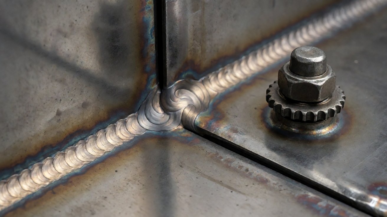
Figure 5: A punched ventilation field on the top cover, with the hole pattern and land width.
Mixing the two is normal: a steel shell with an aluminium front panel and aluminium heat sinks. The joint then becomes a corrosion question as well as a mechanical one, and the two metals need separation or a compatible finish; galvanic behaviour of dissimilar metals is described by ASTM G82.
Shielding Continuity
Shielding only works if the enclosure is electrically continuous, and the requirement for an audio product is normally expressed against CISPR 32 for multimedia equipment. Powder coating is an insulator, so a coated cover screwed to a coated base provides no shielding at all unless the design adds a bonding path: masked contact points, a conductive gasket, or an earth stud that ties the panels together. This is the detail most often missed when an audio chassis is bought on drawing alone.
Ventilation, Welding and Finish
Vent Patterns That Still Shield
Ventilation on an amplifier chassis is where heat and shielding collide. A large open grille cools well and shields badly; a fine perforated field shields better and restricts airflow. The compromise is a punched pattern with a defined land width over the heat sink, intake low at the front and exhaust high at the rear so convection helps. Thermal load is treated in IEC 60890.
Hole size matters in two directions: smaller holes attenuate higher frequencies better and stop a probe reaching a live part, which is why a finger-safe pattern is often specified for install amplifiers. Ingress protection for such openings follows IEC 60529.
Welding, Dressing and Flatness
An amplifier chassis is usually spot welded or TIG welded at the corner seams, then dressed. Weld heat pulls a thin panel, and because the front panel and the top cover are both visible, distortion shows immediately. The sequence that works is to weld the structure, let it cool in the fixture, check flatness against a straight edge, and only then fit the cosmetic panels.
Where a seam will be visible, it is TIG welded and ground flush rather than spot welded, because a spot weld leaves a dimple that the coating cannot hide. Resistance welding practice is described by AWS C1.1. The dressed seam then has to be flat enough that the coating does not telegraph it, which is why dressing and flatness checking are one operation rather than two.
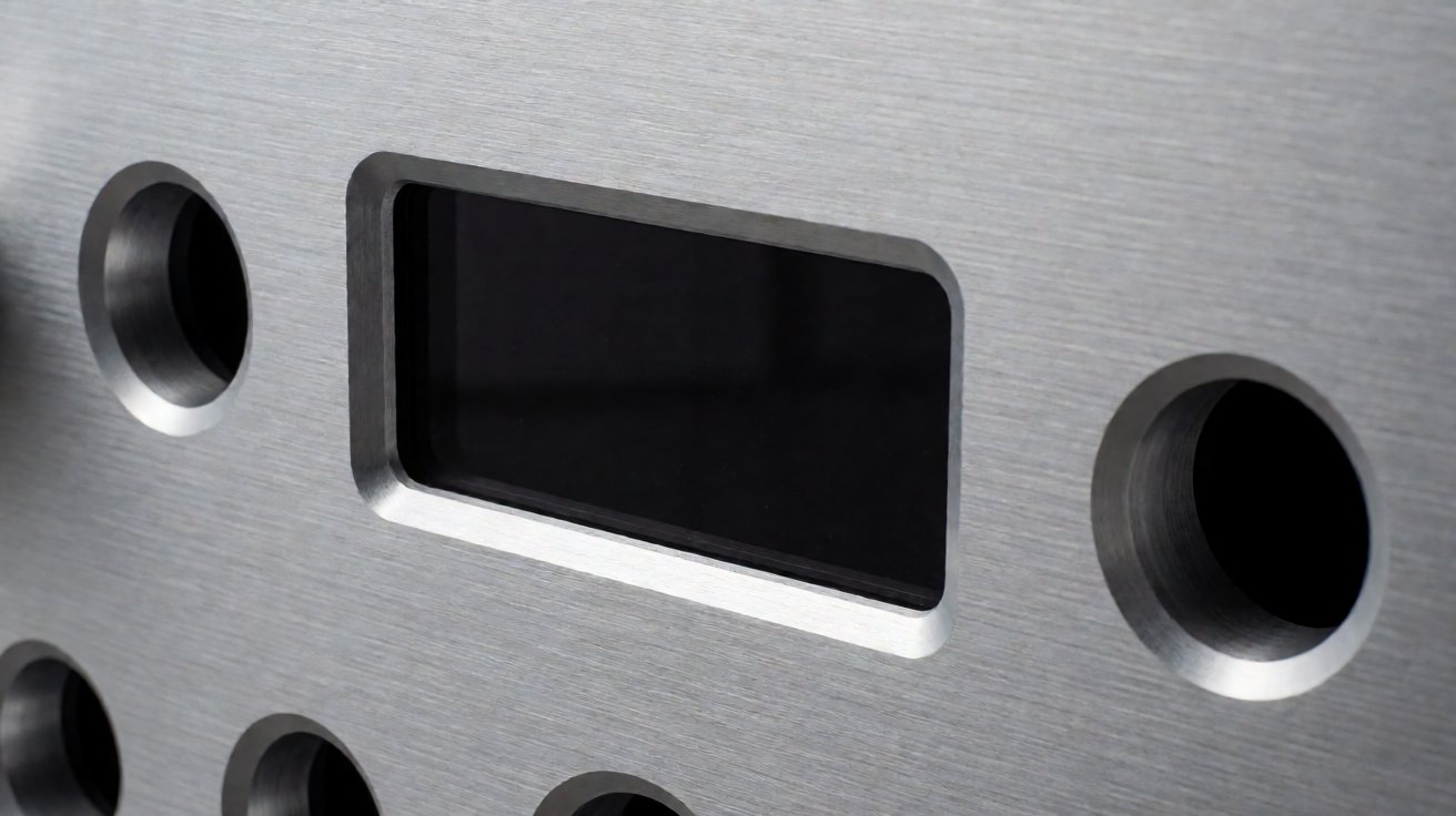
Figure 6: A corner seam welded and dressed before coating, with the earth stud beside it.
Powder Coat, Anodise and Print
Powder coating is the standard finish for an amplifier chassis shell: 60 to 90 microns over pretreatment, in a matte or textured black most often, because a textured surface hides handling marks and reads as a professional product. Durability classes are described by the Powder Coating Institute. The front panel is usually anodised aluminium, with legends either screen printed or laser marked.
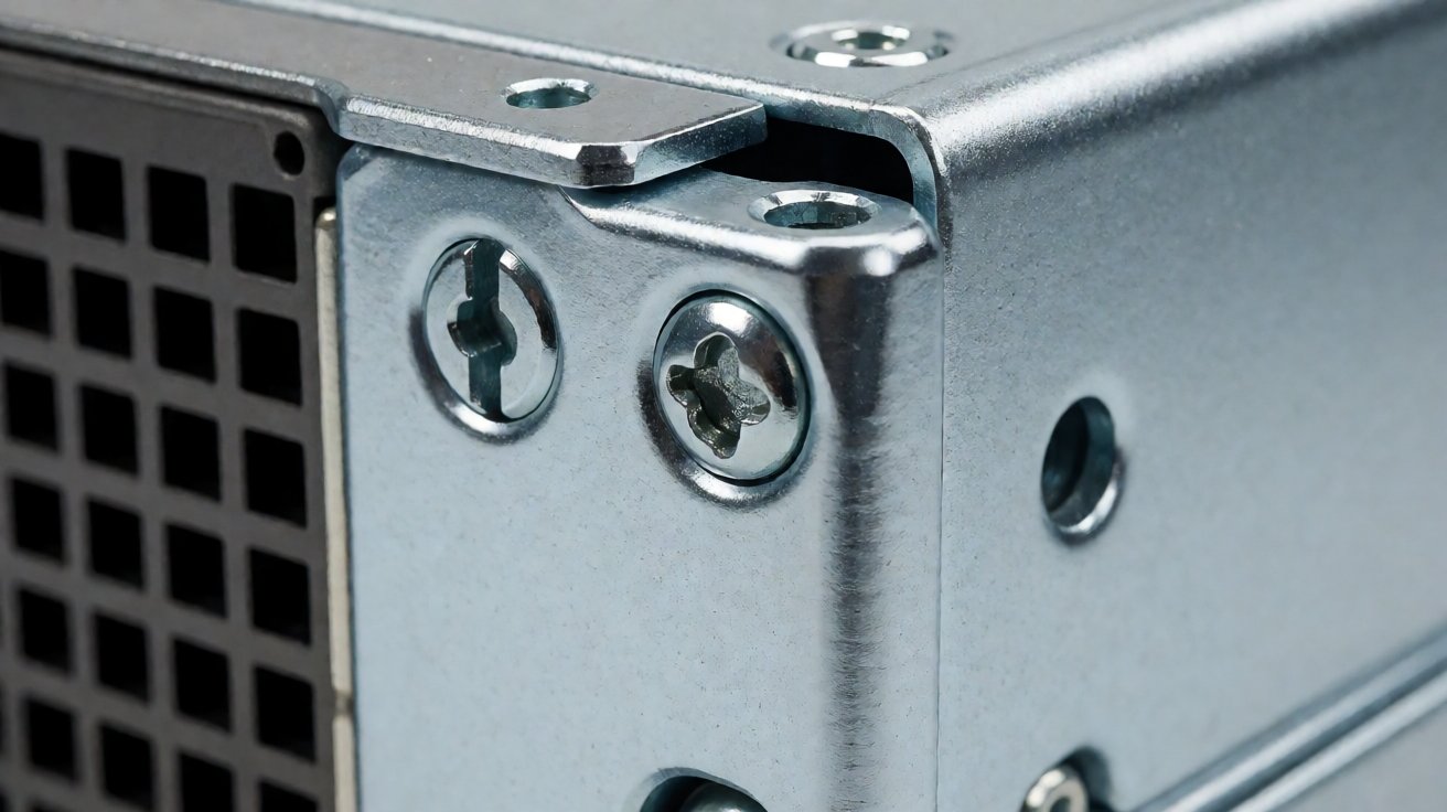
Figure 7: A brushed aluminium front panel with machined openings and printed legends.
Two amplifier chassis finishing details catch people out. Coating build closes small holes and threads if they are not masked, and a coated chassis needs its earth points masked before coating rather than scraped afterwards, because scraping leaves bare steel that rusts. Both are cheap at the design stage and expensive as a rework loop after coating.
Lead Time, Cost and the Order Process
From Drawing to Sample
Amplifier chassis fabrication starts with a drawing package rather than a single part drawing, because the shell, the front panel, the rear panel and the internal brackets have to agree. We ask for the rack height or overall size, the internal components and their mounting points, the heat load, the shielding requirement, the finish and the print artwork.
The review returns the questions that change the design: whether the base needs a rib or a cross-brake, whether the vent field is large enough for the heat load, where the earth points go, and whether the front panel is thick enough to stay flat after machining. It also fixes the order of operations, because a panel that is machined after coating loses its finish and a panel that is coated after machining has to be masked at every opening.
Documents You Should Receive
An amplifier chassis order should arrive with the approved drawing set, material certificates naming the grade, the finish specification with the coating build, and the flatness and dimensional inspection record. Where shielding is specified, the drawing should state the bonding method and the masked areas, because that is a manufacturing instruction rather than a note.
For export programmes the packing method matters as much as the drawing: a coated chassis packed against a carton wall arrives with rub marks on the corner, so panels are foam separated and the front panel is protected separately. Print on a front panel is the most fragile cosmetic on the whole product, and a scuffed legend is a rejected unit.
Batch Sizes and Price Bands
Amplifier chassis are a medium-volume product, and the tooling is modest: a bend program, a punch or laser program and a print screen. A boutique audio brand runs 50 to 200 units per model per year; an install amplifier OEM runs 300 to 1,000. Batches of 100 to 500 are typical, with a minimum order around 50 once the tooling exists. FOB prices for a 2U steel chassis with a coated shell and an anodised front panel typically fall between USD 18 and USD 55 depending on gauge, ribbing, vent area and print.
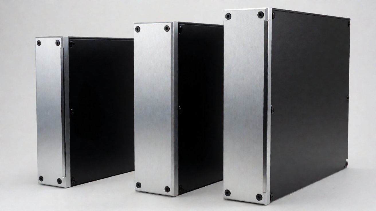
Figure 8: The 19-inch mounting ears and rail fixings, with the rack unit height dimensioned.
Three Amplifier Chassis Programmes
A 2U Install Amplifier for a European Audio Brand
An install audio brand needed a 2U rack chassis for a four-channel amplifier: steel shell, aluminium front panel with a machined recess and printed legends, a vented top over the heat sink, and masked earth points because the unit had to pass an EMC test at the customer’s lab.
We produced the amplifier chassis with a swaged rib across the base, a punched vent field at a defined land width, TIG welded and dressed corner seams, a masked earth stud and an anodised front panel. Releases ran at 250 units, three times a year, with an MOQ of 100 and FOB prices from USD 32 to USD 44. The first batch shipped 25 days after approval and annual value was approximately USD 27,000.
A 1U Rack Processor for a US Pro Audio Maker
A pro audio manufacturer needed a 1U chassis for a digital matrix processor: very shallow depth, a dense front panel with eight connectors and a display window, and a strict flatness requirement because the unit stacked with others in a rack.
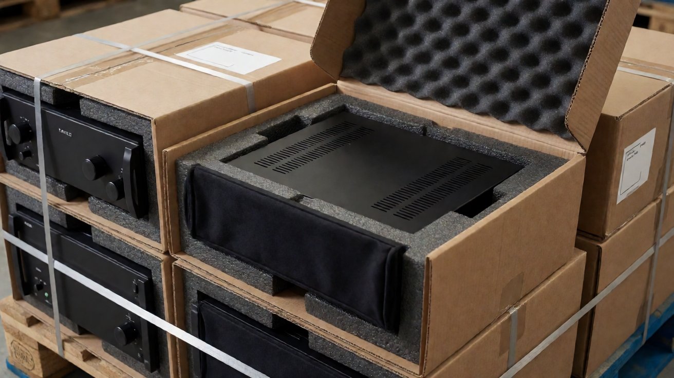
Figure 9: Finished chassis packed in foam-lined cartons for export.
The amplifier chassis was built in 1.2 mm steel with a cross-brake rather than a rib to keep the depth, connector holes punched in one setup, and the front panel surface checked against a straight edge before coating. Releases ran at 400 units, twice a year, with an MOQ of 150 and FOB prices from USD 21 to USD 30. First batch shipped 22 days after approval and annual value was approximately USD 20,000.
A Sealed Marine Audio Housing for an Australian Brand
A marine audio brand needed a housing for a deck-mounted amplifier that would see salt spray: sealed gasket groove, corrosion-resistant finish, no exposed vent, and a heat path through the base into the mounting surface rather than through air.
We fabricated the amplifier chassis in 1.5 mm with a formed gasket groove, sealed fastener points, a super-durable powder coat at 80 to 100 microns and a flat, unvented base for thermal contact. Releases ran at 120 units, twice a year, with an MOQ of 50 and FOB prices from USD 38 to USD 52. The first batch shipped 28 days after approval and annual value was approximately USD 10,000.
Choosing an Amplifier Chassis Supplier
What to Ask at Quotation
Ask five things before comparing prices for an amplifier chassis. Is the base ribbed or plain, and at what gauge? Is the vent area sized to a stated heat load? Are the earth points masked before coating, and is the bonding method on the drawing? Is the front panel flatness specified, and checked before or after finishing? And is the legend screen printed or laser marked?
The answers separate suppliers quickly. A quote that names the gauge, the ribbing, the vent area, the masking and the panel flatness is comparable; a quote that lists a rack height and a price is not, because the same 2U box can be built as a ringing shell or a dead one.
Where Suppliers Fail
Failures in amplifier chassis supply cluster in four places. The cover rings at a particular note because the base was never ribbed. The unit fails EMC because the coated panels were never bonded. The amplifier runs hot because the vent field was copied from a smaller model. The front panel is not flat because it was machined before stress relief. And the earth points rust because they were scraped after coating instead of masked before it.
None of these are exotic. They are the result of treating an audio chassis as a generic box, and they are avoided by putting the stiffness, shielding and thermal requirements into the drawing package.
How XHX Metal Works
XHX Metal has manufactured sheet metal parts and enclosures for export customers from Dongguan since 2014, in a 2,000 sqm factory with about 30 staff and an annual capacity of 500,000 parts. The equipment list covers two 6 kW fiber laser cutting machines at +-0.01 mm, CNC punching, CNC bending, spot and TIG welding, powder coating through audited partners and screen printing, all under ISO 9001:2015 with CE documentation and SGS records. Dimensional inspection practice follows ISO 14253-1.
For an amplifier chassis programme, samples follow in 5 to 10 working days and first batches in 15 to 30 days. Send a drawing or a sample with the rack height, the internal components, the heat load and the finish through the contact page; related work is described on the sheet metal capabilities page and the CNC punching page, and enquiries also reach sales01@xinghaoxin.com.
Frequently Asked Questions
What is an amplifier chassis?
It is the sheet metal housing that carries an audio power amplifier or processor: it locates the transformer, boards and heat sinks, provides the front panel the user sees, and removes the heat those components generate.
What gauge steel is used for an amplifier chassis?
Rack chassis are commonly built from 1.2 mm to 2.0 mm cold rolled steel. Stiffness is better achieved with a rib or a cross-brake than with extra gauge, because thickness adds mass and can lower the resonance into the audible band.
Why does my amplifier chassis ring or buzz?
A large unsupported panel resonates at a frequency that a musical note or the mains transformer can excite. A swaged rib, a folded return flange or a cross-brake raises the panel stiffness and moves that peak out of the band that excites it.
How do you keep shielding when the chassis is powder coated?
Powder coat is an insulator, so the design must add a bonding path: masked contact points before coating, a conductive gasket at the joint, or earth studs tying the panels together. Masking before coating is preferable to scraping afterwards.
Can you supply the front panel with print?
Yes. Front panels are supplied anodised aluminium or powder coated steel, with legends screen printed or laser marked, and machined openings cut in one setup so the connectors and the print stay aligned.
How long does amplifier chassis fabrication take?
Samples follow in 5 to 10 working days after drawing approval. First production batches ship in 15 to 30 days depending on the welding, coating and print content.